Full Matrix Capture (FMC) & Total Focusing Method (TFM): Two Inseparable Brothers! The Phased Array Evolution? (Part. 2)
By: Eng. Jesus Eduardo Contreras
If you belong to the world of Non-Destructive Testing and more specifically, in those techniques related to Ultrasound, most likely, you have recently heard about these 2 inseparable brothers! FULL MATRIX CAPTURE (FMC) and the TOTAL FOCUSING METHOD, let see: What are both techniques and Why are inseparables? In this article let us talk about Total Focusing Method (TFM)
TOTAL FOCUSING METHOD (TFM): Once the data of this matrix is collected, the signal is processed using the TOTAL FOCUSING METHOD (TFM) to produce an image (or Frame) where each pixel is one dedicated and focused focal law in the region of interest (ROI). TFM is particularly useful for reconstructing the data for defect characterization.
Thus, FMC is UT data collection and TFM is data processing! In the figure below (Figure 1), there is a transducer (Probe) with N elements. The probe is over a sample and inside the sample there is defined a zone called Region of Interest (ROI) (Defined through the software):

In this area, P is any pixel defined within the region of interest (ROI)(Figure 2), now from the data captured by the FMC, the Flight of Time (TOF) is calculated for a combination (Ei,Rj) for that point P (See figure 3)

Now the amplitude is extracted from each signal at time tij(P), as follow in the figure 3:
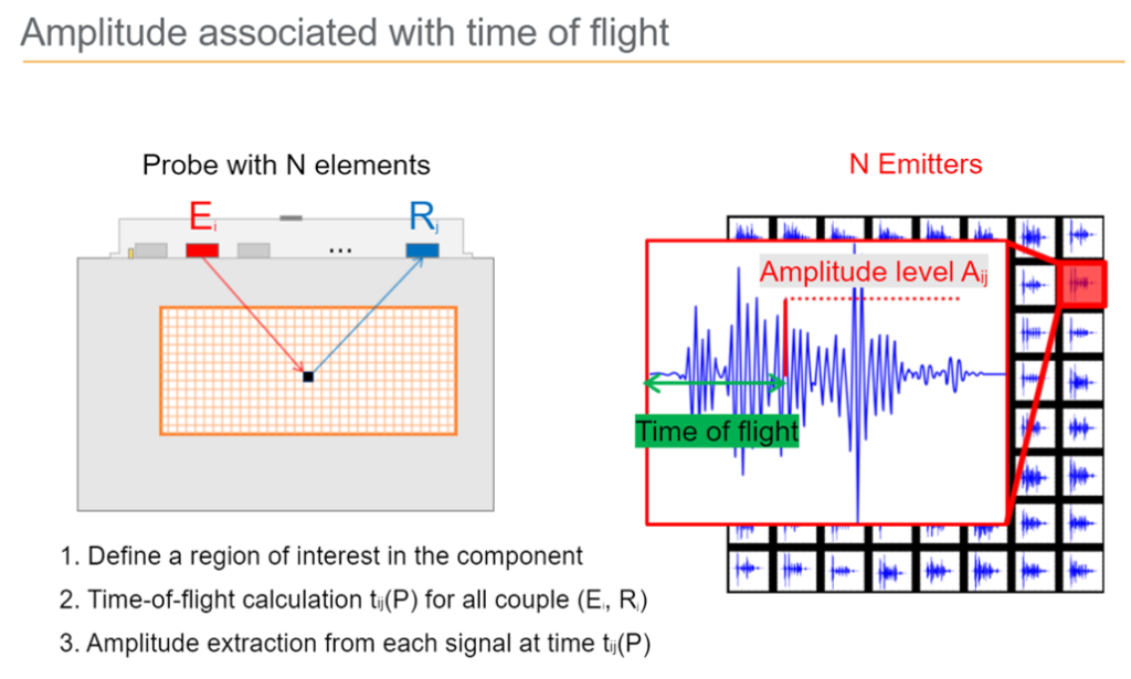
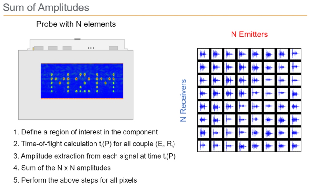
And this is repeated for each signal recollected in the matrix, the amplitude summation gives an amplitude for P (See Figure 4). Doing the same for each pixel (P) in the region of interested (ROI) gives to every pixel has a dedicated focal law perfectly focused to its location.

This results in better definition and localization of defects in all areas of the image due to the energy sent in all directions within the component. An example is used in a calibration block where in the lateral side is drilled the letters M2M (Figure 5). Red is associated with high amplitude that implies material loss, that is the case for each drill side hole forming the words M2M
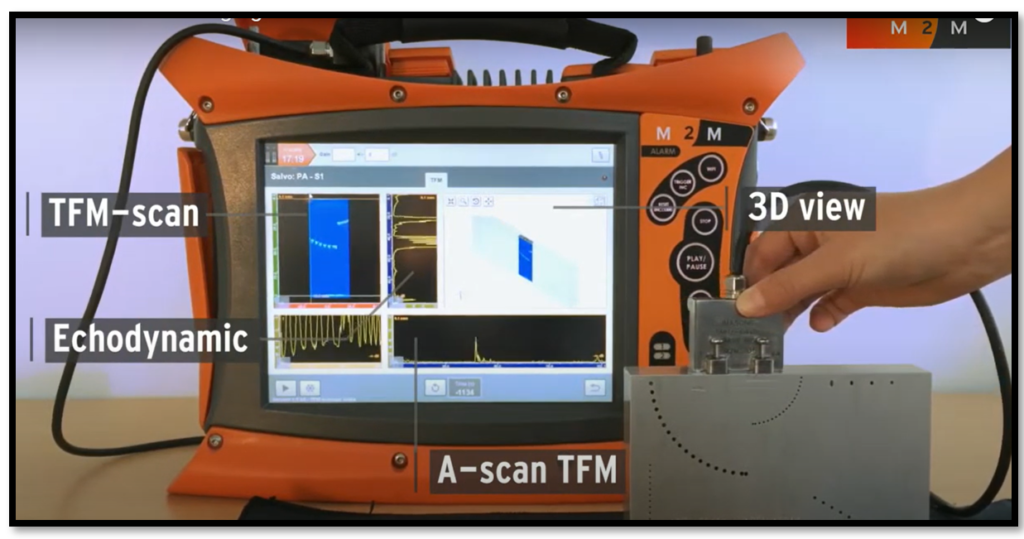
An example more realistic is displayed in this PAUT using a special calibration block (figure 6), where in the layout shown the TFM scan reproduce with high resolution the lateral side drill holes:
Do not miss our article about Total Focusing Method (TFM)! If you want to learn more about these and other techniques, please contact us!


