Non-Destructive Testing (NDT) in Welding Inspection (Part I): General
By: Eng. Jesus Eduardo Contreras
When talking about this topic, we must consider at least 3 important aspects:
i) Welding, which is already an extensive topic, but here we can define very briefly that it is a process that leads to the union of two or more materials together, in such a way that they remain as a single piece. For the purposes of this article, we are talking about metallic materials.
There are many welding processes (At SOLDOZA we are experts in everything related to welding, see references), in other articles we will describe the welding processes in detail.
ii) The defects present in the weld,
as in the previous point, we will detail these defects in other related articles (see references). And the…
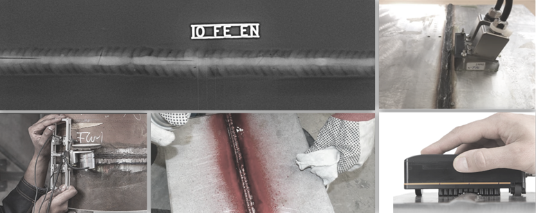
iii) Non-Destructive Testing including:
…techniques both surface detection and volumetric inspection. Each technique has its own advantages and limitations, but in most cases, they can be complementary and combined to provide operators with the most comprehensive data. Thanks to the continued advances in NDT technology enables improved detection of defects and sizing.
Let us start with the most traditional methods to detect volumetric discontinuities:
| Technique | Description | Advantages | Limitations |
| Radiography (RT) | Is the general term given to material inspection methods that are based on the differential absorption of penetrating radiation–either electromagnetic radiation of short wavelength or particulate radiation–by the part or test-piece (object) being inspected. | ||
|
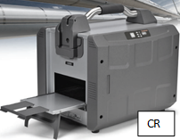
Conventional: X-Ray
|
It detects volumetrics discontinuities such as porosity, inclusions, and even cracks if the crack opening runs parallel to the radiation beam. Can be used on almost any material Well established standards and codes of practice The radiogram or film provides a ‘visual’ indication of flaws |
X-Rays and gamma rays are hazardous radiations Access to both sides of the test object is necessary to produce a radiograph Discontinuities such as cracks, laminations, lack of fusion, etc., must be aligned with or parallel to the radiation beam to be detected clearly Choice of radiation energy for a particular thickness of weld is a critical factor Location of defect in test object’s cross section is difficult to determine |
|
|
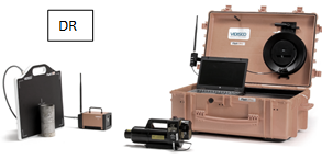
Digital & Computerized
|
On site immediate results Instant image transmission, no developing, no scanning. Results appear on laptop/tablet screen in seconds of shooting Minimal surrounding safety distance No more film consumables (Films paper, Chemicals, etc.) More inspections a day are made possible No more dark rooms Very portable systems |
Less photosensitive than traditional films | |
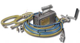
| Ultrasound (UT) |
ULTRASONIC INSPECTION is a nondestructive method in which beams of high-frequency sound waves are introduced into materials for the detection of surface and subsurface flaws in the material. The sound waves travel through the material with some attendant loss of energy (attenuation) and are reflected at interfaces. The reflected beam is displayed and then analyzed to define the presence and location of flaws or discontinuities. |
||
|
Conventional
|
Capable of detecting planar defects not detectable by radiography. High sensitivity, permitting detection of minute defects. Great penetrating power, allowing examination of extremely thick sections, e.g., up to 10 inches of steel. Accuracy in the measurement of flaw position and estimation of flaw size. Fast response, permitting rapid and automated inspection. May be performed with access to only one surface of the object. |
Test conditions which may limit the application of ultrasonic methods usually relate to one of the following factors: Unfavorable geometry of test object; for example, size, contour, complexity and defect orientation. Undesirable material structure; for example, grain size, structure porosity, or inclusion content. Coupling and scanning problems, surface conditions etc. When using normal probes, defects located less than 4-5 mm below the test object’s surface is difficult to detect. (This is due to the equipment dead zone, the width of the pulse, and the probes near zone where interference will affect the measurements). Due to high sensitivity false or irrelevant indications may occur. |
|
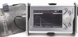
| TOFD |
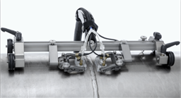
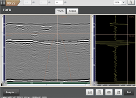
Called Time-of-Flight Diffraction (TOFD) can be used for a variety of applications, its primary use is rapid weld testing of circumferential and axial weld seams
|
Based on diffraction, so relatively indifferent to weld bevel angles and flaw orientation Uses time of arrival of signals received from crack tips for accurate defect positioning and sizing Precise sizing capability makes it an ideal flaw monitoring method Quick to set up and perform an inspection, as a single beam offers a large area of coverage Rapid scanning with imaging and full data recording Can also be used for corrosion inspections Required equipment is more economical than phased array, due to conventional nature (single pulser and receiver) and use of conventional probes Extremely sensitive to all weld flaw types |
Requirement to operator’s qualifications |
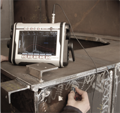
| Phased Array (UTPA) |
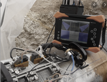
Phased array is an advanced pulse-echo technique utilizing multiple miniaturized transducers and time-delays to shape the ultrasonic sound beam in a desired angle and focus. Therefore, the technique has a wide range of applications Phased array ultrasonic testing (PAUT) probes are composed of several piezoelectric crystals that can transmit/receive independently at different times. To focus the ultrasonic beam, time delays are applied to the elements to create constructive interference of the wavefronts, allowing the energy to be focused on any depth in the test specimen undergoing inspection.
|
PA can reduce inspection times by eliminating or reducing the need for mechanical scanning and by taking advantage of the ability to perform electronic scanning A single phased-array probe allows the user to change the shape and focal point of the ultrasonic beam to optimize each inspection. Digital storage of all data, location, and system settings Visualization of indications in weld and/or base material, using B-, C-, D- and S-scans (with all A-scans included) Compared to measurements with conventional single-element probes, the detection and sizing of defects is much easier and more robust Possibility to facilitate inspections of complex geometries |
Requirement to operator’s qualifications Materials as SS alloys sometimes need special transducers to increase the PoD. Expensive accessories |
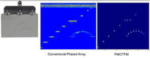
| Total Focus Method (TFM) |
The Total Focusing Method (TFM) is an ultrasonic array technique which is used to synthetically focus on every point of a region of interest
|
Optimal focusing and spatial resolution everywhere Direct imaging of a large area for one probe position All reachable angles with the array simultaneously Defect characterization 3D imaging |
In some application files will be very heavy The data processing speed could be slow in some cases |

Next time, we will be talking about NDT techniques for evaluating surface and sub-surface defects.