Advanced Non-Destructive Testing Techniques for the Detection of Corrosion Under Insulation (CUI) (Part. 2)
By: Eng. Jesus Eduardo Contreras
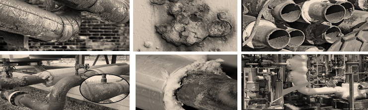
In the past article about CUI, we defined Corrosion Under Insulation (known by its acronym in English, CUI) as a phenomenon that normally affects pipes and pressure equipment made of carbon steel, as a result of the entry or condensation of water under the thermal insulation. Within this category of corrosion can also be included the corrosion generated –for the same cause– under the lagging (CUF, corrosion under fireproofing) of pipes and pressure equipment.
The mechanism of corrosion under insulation involves three requirements:
- Availability of oxygen.
- High temperature.
- Concentration of dissolved species.
How to detect it?
There are a several of techniques available for the detection of this corrosion phenomenon. In these series of articles, we will talk about the 3 techniques most used by a large number of Non-Destructive Testing service companies. The second of them:
The Guided Wave Testing (GWT):
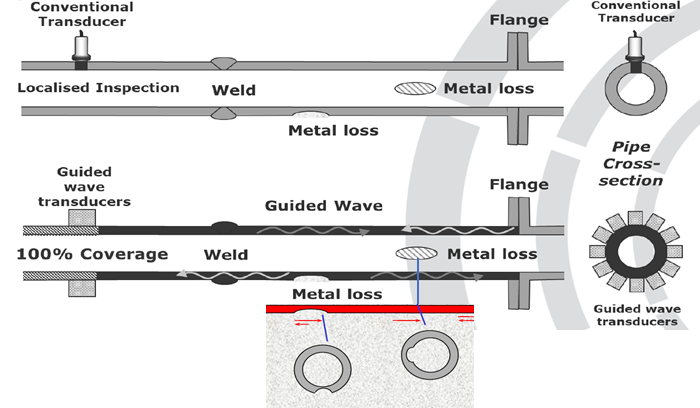
Guided wave ultrasonic testing (GWUT) is considered a fast-screening technique to inspect long distances of a structure, such as aboveground or underground pipelines.
The GWT system uses a pulse-echo method to generate and receive waves by employing rings of transducers that comprise piezoelectric elements embedded at a single transducer location surrounding the pipe circumference (Figure 2). Once the elements are excited equally and simultaneously, an axisymmetric mode is generated and travels along the pipe wall. The locations of internal and external defects in the pipe wall are identified by their reflection arrival time. In contrast to bulk waves, guided waves (GWs) are bounded by the entire wall of the pipe through which they can propagate along the pipe length. Partial reflection occurs when the waves impinge on any features that locally change the pipe geometry, such as pipe welds and defects in the form of corrosion or cracks. Nevertheless, difficulties arise from the irregular shapes of corrosion defects and the complexity of GWs which makes quantitative measurements challenging.
Guided-Wave Examination Method (GWT):
Advantages:
- Can inspect up to 100ft (30m) in each direction away from the transducer array,
- Only ~ 3ft (1m) of insulation need to be removed to attach transducer array,
- Piping from 2” to 48” NPS can be tested,
Disadvantages:
- Limited to applications operating below 125°C, even though there is new development in HT.
- Piping containing high viscosity liquids, heavy external coatings, buried piping, or piping with an excessive number of welds/fittings can reduce the extent of inspection coverage,
- Isolated pitting or corrosion in the immediate vicinity of welds may not be detected,
- Technique is operator dependent
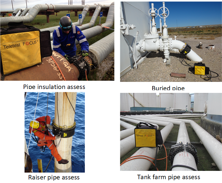
Typical applications:
A case of study
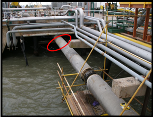
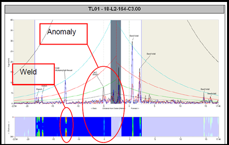
The follow studied case is about two cryogenic JETTY LINES at 8″ and 3″ diameters. The inspection proved to be very successful with 100% of both lines being inspected over a 2-week period. Each JETTY line was approximately 2km in length including several expansion loops and pipe bridges. Several anomalies were identified during the inspection and follow up was conducted whilst the operators were still on-site. The first anomaly identified was located during the opening shot of the inspection; this was of upmost interest to the client as the location; this was of upmost interest to the client as the location was in a difficult to access area seen in figure 3. An anomaly classified as medium priority was identified approximately -3m from the tool position (figure 3).
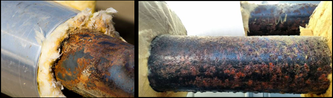
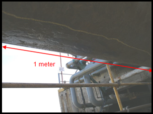
The area of interest was directly above water, so an access platform had to be erected to allow follow up to take place at this location. Upon removal of the insulation the inspection team identified external corrosion at the 180-position seen in figure 4. This area of corrosion was approximately 1m in length and 35% wall loss.
The A-map scan (figure 5) was also used in the identification of this anomaly. The signal from the weld identified at approximately -13m from the tool position does not display an axis-symmetric response. This echo response from the weld signal should be displayed as an even distribution of color representing uniform circumferential signal amplitude. The above gave the operator increased confidence that the signal seen at -3m was in fact attributed to a wall loss defect.
Do not miss the next article about our NDT experiences: Digital radiography (DR) to detect CUI!
If you want to learn more about these and other techniques, please contact us!