Non-Destructive Testing (NDT) in Welding Inspection (Part II): General
By: Eng. Jesus Eduardo Contreras
In the past article we talked about the techniques to inspect volumetrics defect, now…
Let us start with traditional methods and the most recent techniques to detect surface and sub-surface discontinuities:
| Technique | Description | Advantages | Limitations |
|
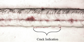
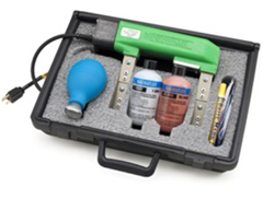
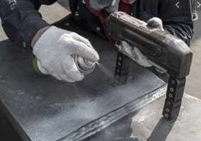
Liquid Penetrant (LT) |
Liquid penetrant testing can be defined as a physical and chemical nondestructive testing procedure designed to detect and expose surface connected discontinuities in nonporous engineering materials The objective of liquid penetrant testing is to provide visual evidence of cracks, porosity, laps, seams, and other surface discontinuities rapidly and economically with a high degree of reliability. With proper technique, liquid penetrant testing will detect a wide variety of discontinuities ranging in size from readily visible to microscopic. |
||
|
|
Liquid penetrant testing is popular because it is relatively easy to use and has a wide range of applications Liquid penetrant testing can quickly examine all the accessible surfaces of objects. Complex shapes can be immersed or sprayed with liquid penetrant to provide complete surface coverage. Because it uses physical and chemical properties rather than electrical or thermal phenomena, it can be used in the field, far from power sources Liquid penetrant testing can detect small surface discontinuities. It is one of the most sensitive nondestructive testing methods for detecting surface discontinuities. Liquid penetrant testing can be used on a wide variety of materials: ferrous and nonferrous metals and alloys Test equipment can be as simple as a small, inexpensive kit of aerosol cans or as extensive as a large mechanized and automated installation Liquid penetrant testing is a direct nondestructive testing method in that the inspector can visually see the discontinuity |
Surfaces of objects to be tested must be clean and free of organic or inorganic contaminants that will prevent interaction of the penetrating media with a surface. Organic surface coatings, such as paint, oil, grease or resin are in this category. Any coating that covers or blocks the discontinuity opening will prevent liquid penetrant entry. Liquid penetrant testing depends on the ability of liquid penetrant to enter and fill discontinuities. Liquid penetrant testing will only reveal discontinuities open to the surface It is also essential that the inside surface of discontinuities be free of materials such as corrosion, combustion products or other contaminants that would restrict entry of liquid penetrant Liquid penetrant testing will not reliably detect discontinuities when it is performed after a mechanical operation or service use that smears or peens the surface liquid penetrant testing is impractical on certain materials, such as some types of anodized aluminum surfaces, other protective coatings and certain nonmetallic parts. Liquid penetrant rapidly enters pores of the material and becomes trapped. |
|
|
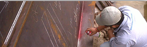
Magnetic Particle Testing (MT) |
Is a nondestructive testing (NDT) method for detecting discontinuities that are primarily linear and located at or near the surface of ferromagnetic components and structures. MT is governed by the laws of magnetism and is therefore restricted to the inspection of materials that can support magnetic flux lines. |
||
|
|
Test results are virtually instantaneous, in that indications will form within one or two seconds of particle application. No developing or processing times are involved. MT can be applied “in-situ,” without the need for an AC power supply, by using permanent magnets or battery-powered yokes. Indications are easy to interpret. The indications formed by the particles closely represent the shape and type of the discontinuity. Training and experience requirements prior to becoming certified are significantly less stringent than for UT, RT, or ET, since MT is a relatively simple process. MT equipment can be much less expensive than other NDT equipment. Depending on the degree of automation or scale of operation, it may also be more economical than many other NDT methods. Virtually any size or shape of component can be inspected. Test part surface preparation is less critical than with penetrant testing. MT can be used to inspect through metallic and nonmetallic coatings or plating with some techniques. It should be noted, however, that a reduction in sensitivity will occur as the thickness of the coating increases. |
It is only effective for the examination of ferromagnetic materials. Discontinuity detection is limited to those at or near the surface. Demagnetization may be required before, between, and after inspections. Discontinuities will only be detected when their major axis interrupts the primary flux lines. This necessitates inspection in more than one direction to assure discontinuity detection regardless of orientation. Some magnetic particle testing techniques may cause damage to the part because of arcing or localized overheating of the parts (for example, when using DC prods). Paint and/or coating removal is necessary from localized areas on the part to facilitate good electrical contact when using direct magnetization techniques. Uniform, predictable flux flow through the parts being tested may not be possible due to complex shapes. Nonrelevant indications due to abrupt changes in component profile or local changes in material properties may make interpretation difficult. |
|
|
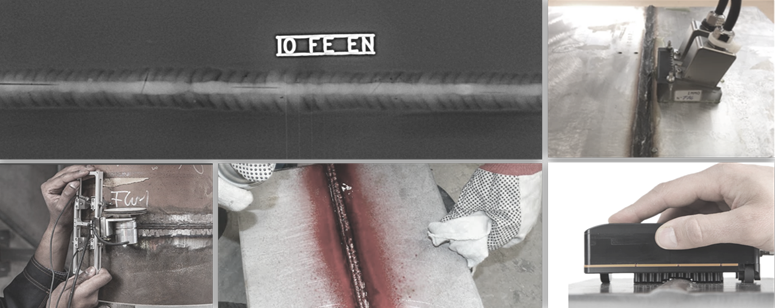
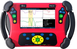
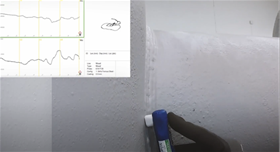
Alternating Current Field Measurement (ACFM) |
Alternating current field measurement (ACFM®) is an electromagnetic inspection technique that introduces an alternating current into the surface of a component to detect surface-breaking cracks. The presence of a crack disturbs the electromagnetic field and the return signal is instantaneously converted by advanced mathematical techniques so that operators are alerted to the presence of defects |
||
|
|
ACFM is a field proven technique for the detection and for the sizing of surface breaking defects in metals It to perform extremely well through coatings even thick coatings and, can size particularly deep defects in large structures. It was originally developed for offshore use to enable divers to detect and sized surface breaking defects are large subsea structures Cost effective and saves time: Very great time-saver when you consider that you don’t have to remove paint and coatings, it means that it’s a big cost benefit over some conventional techniques which will require the removal of coating Proven reliability: its reliability is highly effective and proven through extensive trials Flexible deployment: The deployment of ACFM is very flexible, One man or two person or even remotely deployable through our ROV’s and others robotics systems User-friendly: It’s a very user-friendly technique with very simple scan patterns and understandable data interpretation Auditable data records: Importantly though all of the data that is acquired during the inspection is stored and this allows an audit or review by other experts at a later date Approved by regulatory bodies: The technique is also approved by many regulatory bodies and these are in asset classification societies such as ABS, DNV-GL, Lloyds, ASTM, ASME, ISO |
The initial investment could be high compare with the traditional method. Require a trained inspector Depend on application: Top site or Subsea, changed the accessories (probes) |
|
|
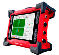
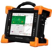
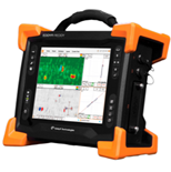
Eddy Current Array (ECA) |
Eddy current array (ECA) technology provides the ability to electronically drive multiple eddy current coils placed side by side in the same probe assembly. Data acquisition is performed by multiplexing the eddy current coils in a special pattern to avoid mutual inductance between the individual coils. Most conventional eddy current flaw detection techniques can be reproduced with an ECA inspection. With the benefits of single-pass coverage, and enhanced imaging capabilities, ECA technology provides a remarkably powerful tool and significant time savings during inspections. |
||
|
|
It is highly effective on coatings/paints Computerized record keeping Easier analysis because of simpler scan patterns (3D/Advance imaging) Is low user/operator dependence It has a remarkably high fast performance (High scanned speed) Low cleaning requirements Eddy current array probes can easily be designed to be flexible or shaped to specifications, making hard-to-reach areas easier to inspect Is possible a post-inspection analysis No use of chemicals/consumables |
The initial investment could be high compare with the traditional method. Requires a trained inspector |
|
|
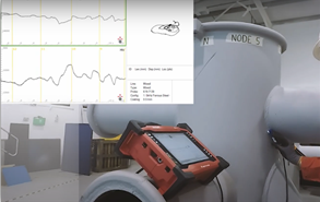
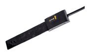
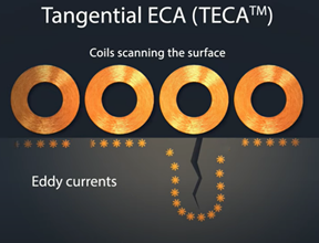
Tangential Eddy Current Array (TECA) |
Tangential Eddy Current Array (TECA™) is a blend of multiplexed tangential coils and pancake coils, specifically designed to detect surface-breaking cracks in carbon steel welds. The TECA coil arrangement and operating mode yield unique eddy current signals from surface-breaking cracks in carbon steel, enabling the sizing of their depth. Transmitters induce eddy currents that flow perpendicular to the direction of scans. When the eddy currents encounter longitudinal cracking, they flow around it by diving underneath or moving around the extremities. |
The initial investment could be high compare with the traditional method. Requires a trained inspector |
|
|
|
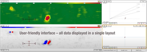
It’s a single pass inspection capability (longitudinal and transverse cracks) Fast – Maximum scan speed of 200 mm/s Wide coverage – The TECA probe has loaded fingers adapt to butt weld crowns, these fingers enable the probe to scan the weld cap, the toe area and the HAZ and a single pass with uniform sensitivity The TECA probe does monitor liftoff in real time during inspection Reliable, less operator depended compared to traditional methods Easy interpretation: The TECA probe also yields a wealth of information through 2D and 3D C-scan imagen. This intuitive imaging offers clear visual indications of defects Measure crack length and depth up to 10mm and paint thickness The entire inspections are easy to record and archive The depth of the crack is sized directly from the eddy current measurement – Not based on theoretical modelling. |


Do you want to know more about ACFM, ECA and TECA? We will be talking more about these techniques in another article!